X
X
R
R
P
P
7
7
7
7
1
1
4
4
Q
Q
u
u
a
a
d
d
C
C
h
h
a
a
n
n
n
n
e
e
l
l
D
D
i
i
g
g
i
i
t
t
a
a
l
l
P
P
W
W
M
M
S
S
t
t
e
e
p
p
D
D
o
o
w
w
n
n
C
C
o
o
n
n
t
t
r
r
o
o
l
l
l
l
e
e
r
r
March 2011
Rev. 1.1.
Exar Corporation
www.exar.com
48720 Kato Road, Fremont CA 94538, USA
Tel. +1 510 668-7000 Fax. +1 510 668-7001
GENERAL DESCRIPTION
The XRP7714 is a quad-output pulse-width
modulated (PWM) step-down DC-DC controller
with a built-in LDO for standby power and
GPIOs. The device provides a complete power
management solution in one IC and is fully
programmable via an I
2
C serial interface.
Independent Digital Pulse Width Modulator
(DPWM) channels regulate output voltages
and provide all required protection functions
such as current limiting and over-voltage
protection.
Each output voltage can be programmed from
0.9V to 5.1V without the need of an external
voltage divider. The wide range of the
programmable DPWM switching frequency
(from 300 KHz to 1.5 MHz) enables the user to
optimize between efficiency and component
size. Input voltage range is from 4.75V to
25V. An I
2
C bus interface is provided to
program the IC as well as to communicate
with the host for fault reporting and handling,
power rail parameters monitoring, etc.
The device offers a complete solution including
independently programmable: soft-start, soft-
stop, start-up delay and ramp of each PWM
regulator.
APPLICATIONS
" Multi Channel Power Supplies
" Audio-Video Equipments
" Industrial & Telecom Equipments
" Processors & DSPs Based Equipments
FEATURES
" 4 Channel Step Down Controller
Programmable Output Voltage 0.9V-5.1V
Programmable 1.5MHz DPWM Frequency
Integrated FET Drivers
" 4.75V to 5.5V and 5.5V to 25V Input
Voltage Range
" Up to 6 Reconfigurable GPIO Pins
" Fully Programmable via I
2
C Interface
" Independent Digital Pulse Width
Modulator (DPWM) channels
" Complete Monitoring and Reporting
" Complete Power Up/Down Sequencing
" Full On Board Protection
OTP, UVLO, OCP and OVP
" Built-in 3.3V/5V LDO
" PowerArchitect" Design Software
" Green/Halogen Free 40-pin TQFN
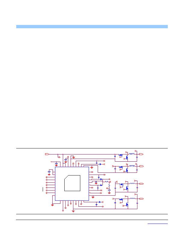
TYPICAL APPLICATION DIAGRAM
Fig. 1: XRP7714 Application Diagram
C
VOUT3
Vout1
VOUT2
LX1
Vout2
Vout3
ENABLE
Vout2
Vout4
GL4
GH4
GPIO2
C11
GPIO3
D3
LX4
Vin
C14
R2
GPIO0
C10
Vin
Vin
Vin
U1
XRP7714
AVDD
1
DVDD
2
GPIO0
3
GPIO1
4
GPIO2
5
GPIO3
6
GPIO4_SDA
7
GPIO5_SCL
8
ENABLE
9
DGND
10
PGND4
21
GL4
22
LX4
23
GH4
24
BST4
25
VCCD
26
BST2
27
GH2
28
LX2
29
GL2
30
Q4
Q3
L2
C7
C6
GH2
LX2
GL2
Q8
Q7
L4
C16
C15
GH3
GL3
LX3
Q6
Q5
L3
C13
C12
GL4
C8
GH4
LX4
GH1
GL1
LX1
C5
Vout3
Vout4
Vout1
GPIO1
SCL
SDA
Q2
Q1
L1
C2
C1
VIN: 4.75 TO 25V
C3
LDO OUT
R1
VCCA
ENABLE
VCCA
VCCD
VOUT1
GL2
LX2
GH2
Exposed Pad: DGND
C9
D2
D1
C4
VOUT4
D4
VCCD
C17
GH3
LX3
VCCD
GH1
GL3
GL1
发布紧急采购,3分钟左右您将得到回复。
相关PDF资料
XRP7740ILB-0X18-F
IC REG 5OUT BCK/LINEAR 40TQFN
XRP7740ILBTR-F
IC REG 5OUT BCK/LINEAR 40TQFN
ZDS1009TA
IC CURRENT MIRROR SOT223-8
ZXCT1008FTA
IC CURRENT MONITOR 1% SOT23-3
ZXCT1009T8TA
IC CURRENT MONITOR 1% SM8
ZXCT1010E5TA
IC CURRENT MONITOR 1% SOT-23-5
ZXCT1011E5TA
IC CURRENT MONITOR 1% SOT23-5
ZXCT1012DAATA
IC CURRENT MONITOR 2.5% 5TDFN
相关代理商/技术参数
XRP7714ILB-0X18-F
功能描述:电压模式 PWM 控制器 4CH DIGITAL PWM CTRL I2C INTERFACE
RoHS:否 制造商:Texas Instruments 输出端数量:1 拓扑结构:Buck 输出电压:34 V 输出电流: 开关频率: 工作电源电压:4.5 V to 5.5 V 电源电流:600 uA 最大工作温度:+ 125 C 最小工作温度:- 40 C 封装 / 箱体:WSON-8 封装:Reel
XRP7714ILB-0X1C-F
功能描述:电压模式 PWM 控制器 4CH DIGITAL PWM CTRL I2C INTERFACE
RoHS:否 制造商:Texas Instruments 输出端数量:1 拓扑结构:Buck 输出电压:34 V 输出电流: 开关频率: 工作电源电压:4.5 V to 5.5 V 电源电流:600 uA 最大工作温度:+ 125 C 最小工作温度:- 40 C 封装 / 箱体:WSON-8 封装:Reel
XRP7714ILB-F
功能描述:软开关 PWM 控制器 4Ch Digital Pwr Cntr w/LDO prog. thru PC
RoHS:否 制造商:Fairchild Semiconductor 输出端数量: 输出电流: 开关频率: 工作电源电压:30 V 电源电流: 最大工作温度:+ 105 C 最小工作温度:- 40 C 安装风格:SMD/SMT 封装 / 箱体:SOIC-8 封装:Reel
XRP7714ILBTR-0X10-F
制造商:EXAR 制造商全称:EXAR 功能描述:Quad Channel Digital PWM Step Down Controller
XRP7714ILBTR-0X14-F
制造商:EXAR 制造商全称:EXAR 功能描述:Quad Channel Digital PWM Step Down Controller
XRP7714ILBTR-0X18-F
制造商:EXAR 制造商全称:EXAR 功能描述:Quad Channel Digital PWM Step Down Controller
XRP7714ILBTR-0X1C-F
制造商:EXAR 制造商全称:EXAR 功能描述:Quad Channel Digital PWM Step Down Controller
XRP7714ILBTR-F
功能描述:直流/直流开关调节器 4Ch Dgtl Pwr Cntrllr w/LDO prog thru PC
RoHS:否 制造商:International Rectifier 最大输入电压:21 V 开关频率:1.5 MHz 输出电压:0.5 V to 0.86 V 输出电流:4 A 输出端数量: 最大工作温度: 安装风格:SMD/SMT 封装 / 箱体:PQFN 4 x 5